
In the world of Wireless trail cameras megapixels and trigger times always seem to get top billing. No one stops to think about the lowly antenna, which is until the camera gets deployed in the field and the signal strength leaves something to be desired. At that moment all eyes turn to that little rubber coated protrusion coming out the top of the camera. Luckily there are several options available to anyone that encounters this situation. The solutions range from very inexpensive and easy to install, to a bit more of an investment in time and funds. With this in mind, the following is a guide to all things antennas, at least as they relate to trail cameras. Before we get any further let’s get some of the technical details in order. If this all starts to seem too much like a radio frequency engineering lecture, fear not, the comparisons below will be based in real world conclusions. We just need to understand the basics of the terminology so that the reference figures aren’t coming out of nowhere. The only real figure we need to be familiar with is the dBm, this stands for decibel of radio power per one milliwatt. The power range that we will be discussing, will be from approximately -60 dBm to around -113 dBm. These figures are approximate values not absolute thresholds. A real world example of signal strength would be -87 dBm, which is where most cell phones or wireless trail cameras will show full signal. Considering -60 is a near perfect signal we can then say full signal on a 5 bar signal indicator would be between -60dBM to -87dBm. This of course would be the ideal range that we would like the signal to reach. On the other end of the spectrum would be -113 dBm which is the approximate value where a cellular connection can’t be maintained, let’s call this the bottom of one bar limit. All of the other figures relating to how many bars of signal are achieved at what dBm value are much harder to pin down as they vary from model to model based on the manufactures desires. In other words what is 3 bars on one model may not be 3 bars on another model. The most important thing to take away from all of these numbers is that the measurements are on an exponential (logarithmic to be accurate) scale. This means that relatively small numeric gains represent large actual signal improvements. For the sake of having some real world application let’s just say that most wireless trail cameras need at least 3 bars of steady signal to function reliably with a decent transmission time.
The Enhanced Antenna: A step in the right direction
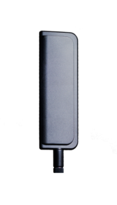 Let’s start with the simple solution. For a slight boost in reception with almost no effort to install and very little funds spent, consider the enhanced antenna. This antenna is a simple screw on replacement of the original antenna. It can provide perhaps 3dBm, at most, of signal improvement. More importantly it has an adjustable joint near the base that allows the antenna to be adjusted into several different positions. This allows the antenna to be positioned away from objects such as trees that could be blocking signal strength. This antenna is best used in a situation where the signal reception is already sufficient, however additional gains are being sought to improve transmission times. This antenna is not a good choice if then signal reception is very poor to start with as it will most likely not produce the gains necessary to make the camera function properly. All of our MINE and ICE cameras have this as the standard paddle antenna.
Real world improvement: .5-1 bar of signal. Actual signal improvement: 1-3 dBm
The Booster Antenna: Now we’re getting somewhere
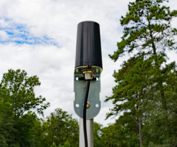 The next solution would be the booster or extended range antenna. This antenna has several significant improvements over the stock or enhanced antennas. First, the actual antenna itself is significantly larger in length and diameter. This is definitely a case where bigger is better. Secondly, and in some ways more important, is the fact that this antenna is a remote mount with a cable attachment. This allows for significant flexibility in where the antenna is placed. No longer is the antenna directly on top of the camera, now it can be placed away from potential signal interference or signal blocking objects. Be careful though, cabling is both friend and foe as it causes signal loss over its length. In this case the cabling type is RG58 cable which has around .18 dBm signal loss per foot. Since there is almost 10.5 ft of cable the approximate signal loss due to cabling is 1.8 dBm. On the plus side the antenna generates over 6 dBm of signal improvement. This takes the total improvement to almost 6dBm. Remember what was said about gains being exponential, right?
Real world improvement: 1-1.5 bars. Actual signal gain: 5.12-6.12 dBm
- Frequency 850/1900MHz
- Impedance 50 ohms
- 824-894 MHz Gain 5.12 dBi
- 1850-1990 MHz Gain 6.12 dBi
- Radiation Omni
- Polarization Vertical
- Wavelength 0.9 Wavelength 824-894 MHz
- 1.95 Wavelength 1850-1990 MHz
- Ground Plane Built-in Ground Plane
- Connector SMA Male
- Material Whip – Stainless Steel / Extension – Fiberglass
- Coaxial Cable RG58 − 10.5 feet / 3.2 meters
- Height 32.0625 inches / 81.45 cm
The Directional Antenna: When “I really want my wireless camera to work”
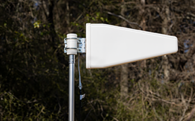 Finally we come to the high gain directional antenna. Up to this point all the antenna options have been non directional, meaning they don’t care what direction the signal comes from. In order to produce the best gains an antenna needs to be unidirectional, meaning it must be aimed directly at the transmission source. With this antenna it is held straight out and moved in 10 degree increments until a signal peak is detected. This peak represents the direction of a cellular transmitter. Research your area for the nearest and most compatible tower available, you can also visit http://www.antennasearch.com/. We also use an app called “Open Signal” which has an option that points in the general direction of the nearest tower. For best results a complete 360 degree circle should be made as there could be multiple towers to receive from and there could also be a peak when the antenna is facing exactly away from the antenna as it is perfectly lined up but facing away. This “back course” peak would obviously be much weaker as the antenna is designed to be pointed at the tower not away from it. Similar to the magnetic antenna, the directional antenna is a remote mounted design. This time the antenna comes with 15 feet of RG58 cable. This is necessary when using longer lengths as RG58 loses only .18 dBm per foot. Using 15 ft of included cable gives us around 2.7 dBm of signal loss. However the directional antenna produces a whopping 11 dBm of signal improvement. This provides a net gain of 8.3 dBm. Make no mistake, this is a lot of signal improvement. This means that if any signal is present in the area of deployment, this antenna can be used to make the camera transmit successfully. Finally there is an intangible factor to be considered with any remote mounted antenna, altitude. Altitude does wonderful things for cellular reception. Since cellular transmissions are a high frequency, short wave length type of signal, they do not adhere to the curvature of the earth. That means, that for all practical purposes, cellular transmissions are line-of-sight signals. Having the ability to mount the antenna almost 15 ft higher than the camera can provide a huge boost to usable signal, simply because it has a better “view” of the cellular tower that it is pointed at. This altitude gain can also compensate some amount of terrain blocking due to hills or valleys. Having said that, it won’t compensate for placing the camera in a deep ravine, remember there has to be some signal present for any antenna to work as they don’t invent signal, they just receive the ambient signal with more efficiency. The directional antenna comes standard it what is affectionately referred to as “snow camo”. However it readily accepts a customized finish from a can of spray paint or any other type of crafty finish that can be thought up. Keep in mind that it is an antenna, so things like metallic paint (seriously metallic paint for camo?) or large amounts of items adhered to the antenna for camo should be avoided. The best results seem to come from the obvious color choices such as OD green, tan and brown. A single color or combination of these colors based upon the area of deployment, go surprisingly far in making this antenna blend in.
Real world improvement 1.5-2 bars. Actual signal gain: 8.3 dBm
The information provided is informational or educational in nature. Signal reception is inherently variable, therefore the facts and figures are based upon the rated specifications of the products. This in no way guarantees that any antenna solution will fix a signal reception problem. The end user is responsible for accessing the reception in their deployment area, considering the antenna specifications and determining the correct solution. In other words “Your mileage may vary”.
Last Update: 01.10.2024