We receive a lot of phone calls when someone is syncing, pairing or timing their camera to the control box. In essence, it’s a simple process by pushing 3 buttons to complete the syncing process.
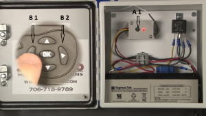 Our basic steps for the syncing process are to open the control box and ensure the battery is attached. Make sure the camera is in the setup mode. Press and release the button inside the control box (A1) and the red light will come on, while the red light is on, press and release the left arrow (B1) then press and release the right arrow (B2) on the camera, it will say “RF trigger” on the screen and the red light inside the control box will blink 3 times and go out. This confirms that the process is complete.
RF Trigger
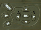 I generally tell everyone to practice step 2 first since this one requires a bit of timing. While the camera is in setup mode (it doesn’t matter if you have signal or not yet), on either side of “OK”, press and release the left arrow (A) then press and release the right arrow (B). Don’t get the right arrow confused with the playback button which is just below the “MENU” button and not on either side of the “OK” button. Look for it to say “RF Trigger” in the bottom center of the screen. Be aware that it will “BLINK” for a few milliseconds and go out. If you don’t see “RF Trigger”, then you may be doing it too slow, try pressing the left and right arrows as quick as possible. Repeat the process, left then right until you see “RF Trigger” blink on the bottom center of the screen. Once you do see it, do it again, get the feel for it and make sure the timing is correct.
(THIS STEP IS ONLY A FUNCTION OF THE M.I.N.E.®, LIVE STREAM CAMERAS.)
The Live Stream Camera has an internal transmitter on the circuit board and must be located within 50 yards of the M.I.N.E.® Gate to operate correctly. Users must manually pair or sync camera transmitter signal to each control box receiver the first time they are linked together. It is not necessary to pair or sync camera transmitter to receiver more than one time. Pressing and holding the Pair to Transmit button for 8 seconds will clear out the memory.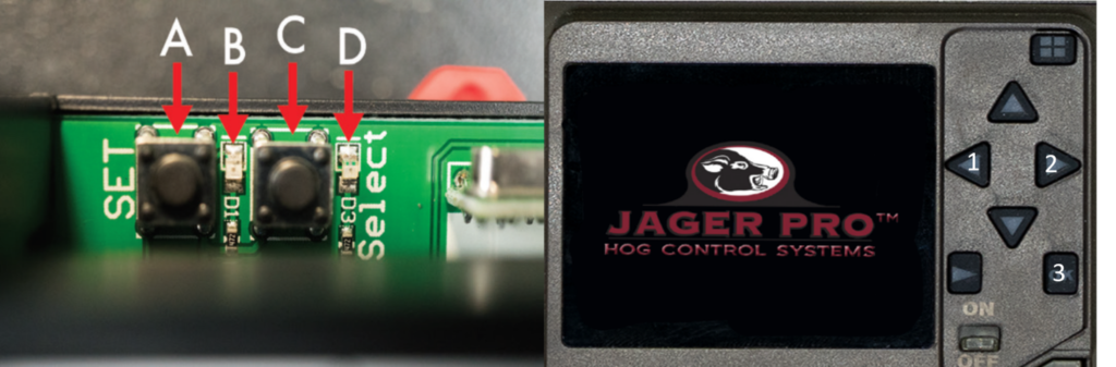
Syncing Process:
- Press and release “frequency select” button (C) and red light (B) will flash either three times or five times. Press and release “frequency select” button (C) until red light (B) only flashes three times.
- Move camera selector switch from OFF to On.
- Press and release “pair to transmit” button (A) and red light (B) will illuminate for 15 seconds. Users only have 15 seconds to complete step 4 once step 3 has been initiated.
- Press and release camera “left arrow” (1) then press and release camera “right arrow” (2) to open the Radio Frequency (RF) page. A message will appear “Please press OK to trigger RF”. Press OK (3) and you will receive a message “RF Trigger…”, your camera should now be linked to the gate transmitter. Red receiver light (B) should flash five times then no longer illuminate.
- Ensure M.I.N.E.® Camera and receiver are paired. Press the OK (3) button while observing green light (D) illuminates. Test successful. Press menu to exit the RF page.
***Repeat these steps on other control box receivers if multiple gates are used at trap enclosure.
Sync
Now that you have mastered the second step, going to step one is a simple press and release of the button inside the control box on the receiver. The red light comes on and only stays on for approximately 15 seconds, our older receivers would only stay on for about 5 seconds. While that red light is on, press and release the left arrow then the right arrow, you will see “RF Trigger” on the screen and the light will blink 3 times and go out. If you don’t see “RF Trigger” and/or the light doesn’t blink, you still have time to press the left and right arrows again.
Confirm
Once the light inside the control box blinks 3 times and goes out, double check to make sure the syncing process is complete by pressing the left and right arrows again, be careful if the gate is up and stand clear, the gate will fall or the actuator will activate letting you know the process is complete. The last step is to set the camera up in position, turn it on and wait about 2 minutes before sending it the proper code to close the gate, the gate should fall approximately 10-20 seconds after the signal is sent (depending on the signal strength in your area).
Make sure the onsite remote is synced with the control box. Press the button on the remote and the red light will come on and should drop the gate, if it doesn’t drop the gate then you will need to sync it with the control box. Press and release the button inside the control box and the red light will come on. While the red light is on, press the button on the transmitter until the light comes on, the light inside the control box will blink 3 times and go out, syncing is complete. Press the button on the remote again to confirm that it is synced. Some of the onsite remotes require you to push and hold the button for 2 seconds for the light to come on. If the light doesn’t come on with the onsite remote, it may be time for a new battery.
Helpful tips
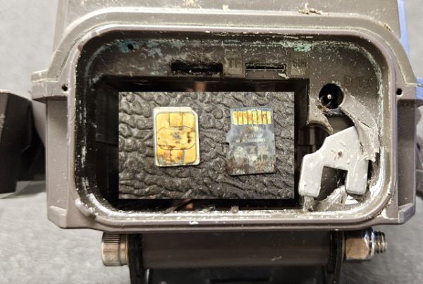
Our camera is the transmitter and has it built inside the camera housing, it will broadcast the signal beyond 90 feet without an antenna. Generally, the trap diameter would be about 40 feet from one end to the other and if the camera is set up across from the gate you should have no problems sending or receiving the signal.
The control box has several different components, the receiver with the button and red light, the AU7 in the top right where all the connections lead to, the bridge in the middle and the blue actuator in the bottom that pulls the rod to close the gate. The actuator requires 11.8 volts or better to operate, anything less and it will not have enough power to drop the gate. 11.8 volts is important to remember since the red light will come on when the button is pushed and you can sync the gate with less than 11.8 volts, the receiver will still respond at less voltage and send the signal to drop the gate but the gate won’t drop due to the low voltage. If the red light doesn’t come on when the button is pushed, make sure the battery leads are hooked up and that the battery is fully charged with 12.5 volts or better. Sometimes during transport one of the leads can come loose, reach inside and gently tug on the wires going into the bridge, make sure none of them are loose. Make sure the antenna from the receiver is threaded properly outside of the box to receive the signal from the camera or onsite remote.
The receiver can manually clear out it’s memory by pressing and holding the button for 8 seconds, the red light will blink 4 times and go out, this lets you know that the memory is clear. This is also an important factor since you don’t want to press and hold the button while attempting to sync them. Once the syncing process is complete, it will retain the cameras transmitter code in its memory and will not need to be re-synced ever again (even after a year with no battery power hooked up to it). You still want to test it if the gate has been out of use by pressing and releasing the left and right arrows from the camera after everything is hooked back up.
Make sure you practice step 2 before going through the entire syncing process and you shouldn’t have any problems syncing your camera to your control box. You can sync multiple control boxes to one camera and have a simultaneous drop of 2 or more gates. It’s also a good idea to maintain control of the onsite remote and use it for testing or dropping the gate when needed.
Visit our trapping manual and camera manuals for further details.